|
Raster Tab
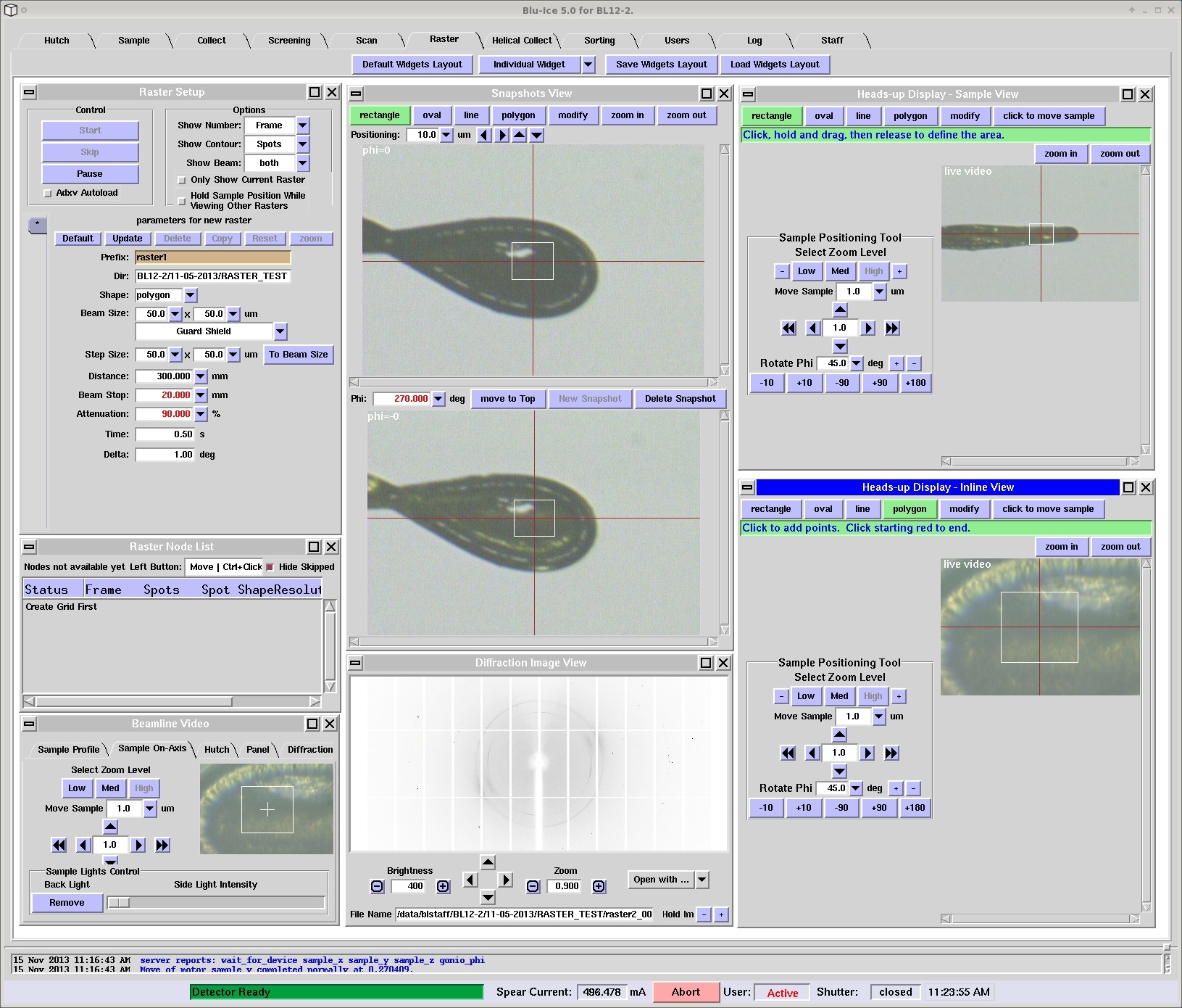
OverviewThe Raster tab allows the user to search for and align crystals based on low level diffraction. This is carried out by defining a 3-dimensional raster, recording low level diffraction images, and then processing them with "Spotfinder" using a specialized input file tailored for weak low resolution spots and detector characteristics. If your crystal is too small to see with the video system, obscured by ice or cryo-protectant, or has some visible defects or satellite crystals, then using the Raster tab will help you locate the crystals and/or chose the best part of the crystal to shoot. The new rastering tab makes the procedure more manual and allows various new options to collect data. The Raster Tab is composed of individual widgets that can be moved, hidden or displayed by choice. The layout displayed in Figure 1 shows all the available widgets: Raster Setup, Snapshots View, Heads-up Display - Sample View, Heads-up Display Inline View (only on BL12-2), Raster Node List, Beamline Video, and Diffraction Image View.
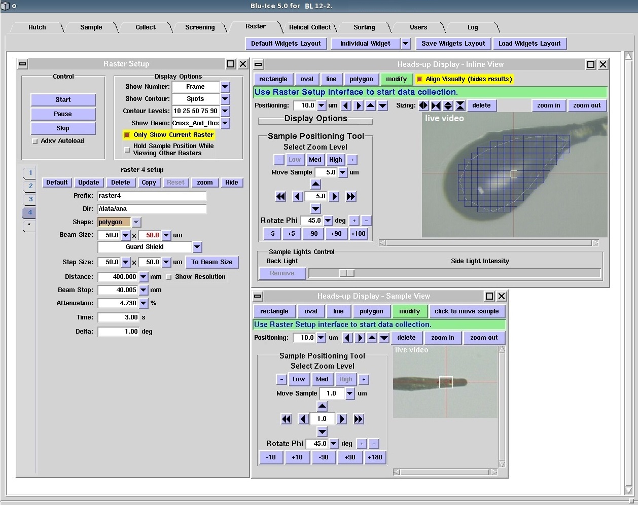
Raster tab widgetsClicking on the Default Widgets Layout will display the default widgets: Raster Setup, Heads-up Display - Inline View (which shows the sample as viewed from the beam direction, only on BL12-2) Raster Node List, and Diffraction Image View. The Individual Widget button allows customized display of each widget. The full widget list can be accessed from the drop down menu. Save Widgets Layout will save the current tab layout in a file in the user's home area, which can be subsequently redisplayed with the Load Widgets Layout button. The Raster Setup widget displays the parameters for the selected raster and has clickable buttons to Start, Skip and Pause the rastering operation. The Options section on this widgets enables control of the items displayed (number of spots, Resolution, score, etc.) in the Heads-up Display for a completed raster run. The raster run setup section at he bottom of the widget allows renaming of the raster diffraction images and control of the beamline parameters (beam size, detector distance, exposure, delta phi etc.) used to collect the raster diffraction images. Default parameters for the directory and image name, beam size, exposure time and delta phi are entered by using the Default button. The Update button sets the values for the beam size, detector and beamstop distance and attenuation to their current value; typically these button should only be used when starting the set the rastering run (they will *not* move the motors to the entered position). The Delete button will erase both the raster parameters and the shape drawn in the Heads-up Display; once a a rastering run has started, the Reset button must be used before the run can be deleted or modified. A new run can be defined while clicking on the * tab below the last used run. Check the Only Show Current Raster input button to hide rasters defined from a previously defined run when setting up a new one. Otherwise, the Heads-up Display will show all the rasters set up for the crystal. Also, to avoid the sample being translated to the position used to set up previous runs, click the Hold Sample Position While Viewing Other Rasters checkbox (this will still rotate phi). Selecting the raster areaA typical rastering operation starts by selecting an area of the crystal or loop using either the Heads-up Display - Inline View (available on BL12-2) or the Heads-up Display - Sample View. This area can be selected as a rectangle, oval shape, line, or polygon (Note: Use polygon to draw any shape.). To draw them on the crystal view, first select the shape (rectangle, oval, line, or polygon) and move the mouse to where you want to start drawing the shape. Use the left mouse button to draw the shape. The selection of a rastering area using the "Polygon" option on the "Heads-up Display-Inline View" is shown in Figure 2. The Heads-up Display - Sample View shows the the crystal from below (90 degrees from the beam axis) and the selected rastering area (Figure 2).
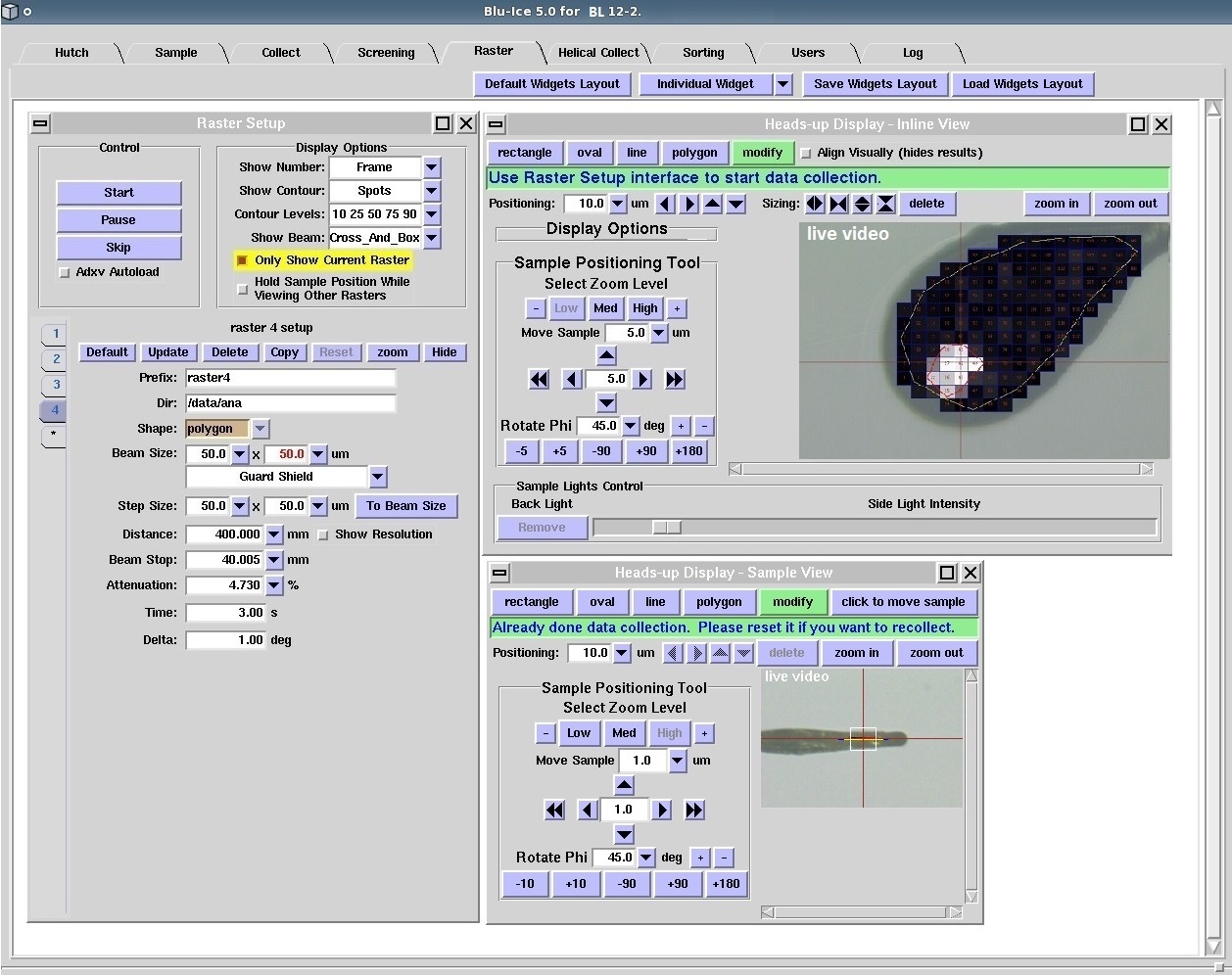
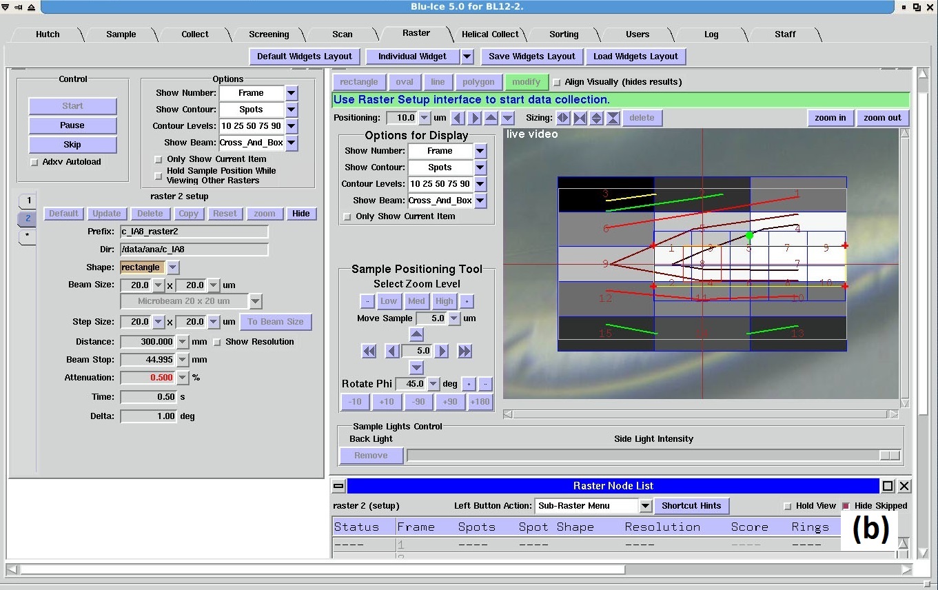
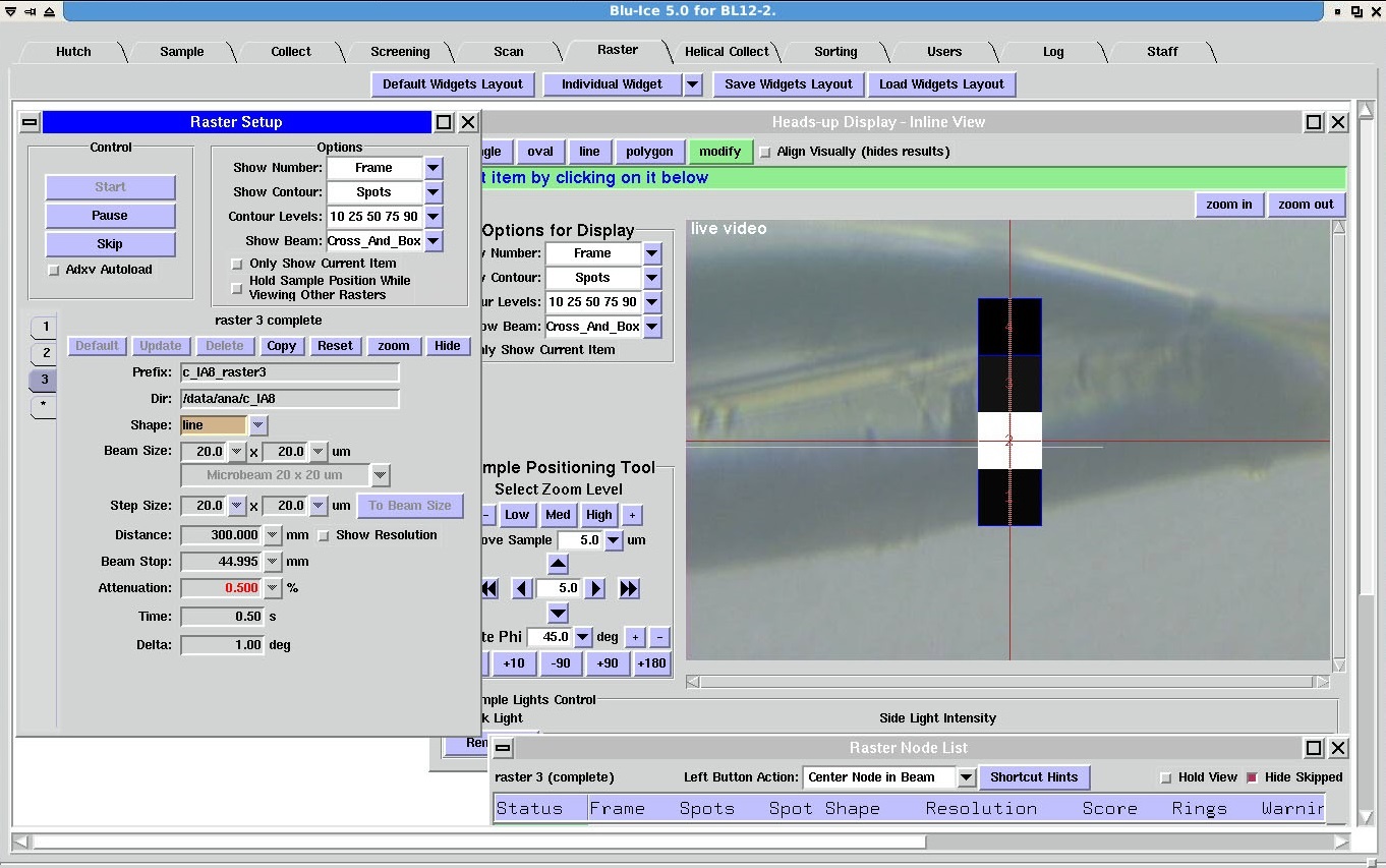
Once we finish drawing the selected area, the modify button becomes active and enable fine tuning of the selected area. The submenu that appears upon clicking the button contains a Delete button that can be used to erase the drawn form and start the selection all over. The selected area is shown with blue, yellow, and green colors (Figure 2), with red crosses at the corners. The blue lines show the beam size and the yellow lines show the edges of the selected polygon. Clicking on the blue line with the left mouse button and moving the mouse with the left mouse button pressed moves the selected area. Clicking on a red cross with the left mouse button and moving the mouse with the left mouse button pressed changes the shape of the polygon. Clicking on the green circle with the left mouse button and moving the mouse with the left mouse button pressed rotates the selected area. The beam area and position are shown by default as a white box and the intersection of the two red lines bisecting the screen, which can be selectively hidden with the Show Beam menu. Setting the raster run parametersAfter the selection of the rastering area, the Raster Setup widget automatically creates a new run for the new rastering area (Figure 2). Set the file prefix, proper directory, detector and beam stop distance, attenuation, exposure time and delta phi for rastering. This view also shows the selected shape of the rastering area (Polygon), beam size, selected collimator, and step size. The collimator selection option is visible only at beamline 12-2. At beamline 12-2, we can select Guard Shield or any of the available microcollimators. The option shown in the figure is "Guard Shield". If we change this to one of the microcollimators, the change will be instantly reflected on the selected rastering area (Inline View) with many more blue squares indicating the smaller beam size. If we rotate phi, the selected rastering region also rotates. Raster operationPressing the Start button in the Raster Setup widget starts the rastering operation. Note that in the Sample Camera view, the sample will be rotated 90 degrees to face the beam, and then rotated back once rastering is finished. A view of the rastering tab after data collection is shown in Figure 3. The Heads-up Display views show the rastered region highlighting the number of spots or any other information selected by the user. During the rastering operation, the selected rastering shape will move to each position indicating an exposure in that region. The Diffraction Image View will also get updated with new images during the rastering operation.
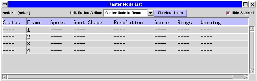
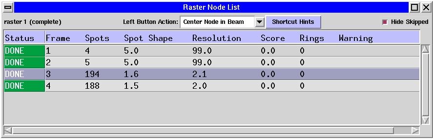
The program also updates the information in the Raster Node List just after selecting an area for rastering (Figure 4, left panel). The information in the Raster Node List gets constantly updated during rastering and also after the rastering operation (Figure 4, right panel). The "Left Button Action" section in the Raster Node List widget has a pull-down menu to select <>Center Node in Beam (to center the portion of the crystal representing that node), Send to ADXV (opens the corresponding image in a new adxv window), ADXV and Center (opens the corresponding image in a adxv window and centers that portion of the crystal), Sub-Raster Menu (gives options to do a line raster perpendicular to the selected area or a rectangle raster with minimum beam size). To activate an option, first select the option from the pull-down menu and click anywhere on the node line with left mouse button. There is also a shortcut to go to some of these options (Cntrl+click to Center Node in Beam, shift+click to Send to ADXV, and Right click to access Sub-Raster Menu) and this information can be seen by clicking on the Shortcut Hints button.
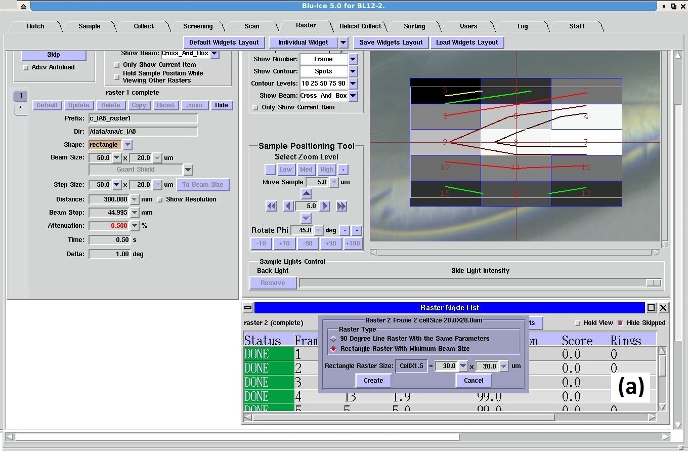
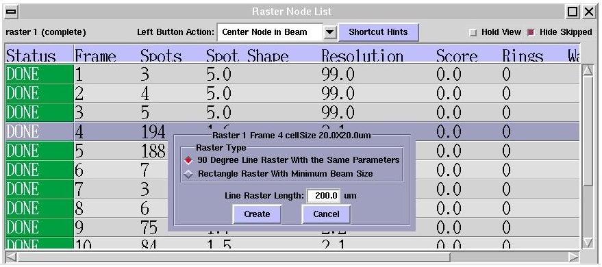
After the rastering operation, the current raster view becomes inactive. To delete this raster, first click on the Reset button in the "Raster Setup" widget. A specific part of the rastered region can also centered by first clicking on the click to move sample and then clicking on the area in the "Heads-up Displays". The Sub-raster menuThe Sub-Raster Menu gives options to do a rectangular rastering with the minimum beam size around a specific node or a linear rastering perpendicular to it. Right+click on the "Raster Node List" widget opens this menu. After the initial raster is done (Figure 5a), you have the option to set up a finer raster about the best nodes by selecting the Rectangle raster with minimum beam size option in the Sub-raster menu (Figure 5b). The rastering area is defined by default as a rectangle of 1.5 x(beam with, beam height) centered in the selected node and with a step size equal to the minimum beam size. The corresponding run is created by clicking the Create button (Figure 5a). Once the raster operation is complete, the crystal can be centered along this direction in the same way as in the first area raster.
Once the raster in one direction is completed and the crystal centered in the beam, it is possible to raster in the perpendicular direction using the "90 degree line raster with the same parameters" option in the Sub-raster menu.
Displaying previous rastersClicking on each of the runs in the Raster Setup widget will display the selected raster run. The display option Only show current raster will hide all the other rasters donde in the same orientation, and the Hold sample position will stop the sample translation when selecting other rasters. |
|||
|
|
|||
| Technical questions: Webmaster
Content
questions: Irimpan Mathews |
|||
| Last modified:Thursday, 28-Mar-2024 10:36:20 PDT. | |||