Heat Shield Assembly - Illustrated Guide.
For instructions for the heating shield replacement see general information about the heating shield.
1.1. Assembly tools
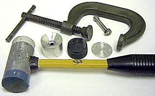
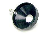
To assemble the heat shield, you need a hammer (preferably with a plastic tip), a C-clamp, a steel rod 8 to 10 mm in diameter (may be replaced with a 5mm screw with a nut), a wise, two steel balls 3 and 6 mm in diameter, a cone-shaped support block (see Drawing), a conical rubber plug (see Drawing) and a round pressure plate (see Drawing). A picture below shows the tools used.
1.2. The assembly procedure.
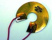
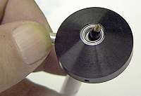
1.2.1. Attach the wire guide to the shield body.
Insert the tip of the wire guide into the hole in the heat shield body side wall. Squish the inner part of the guide sideways using a 3mm (1/8") ball and a wise. Then repeat the same operation with a larger (6-8 mm) ball to smooth the edges. The result is shown on the picture to the left. The wire guide should be reliably attached without any play.
|
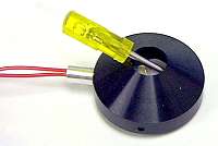
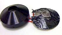
1.2.2. Shape the heating element.
The heating element (below, left) has a 50° open sector, which allows wrapping it into a cone with a cone angle of 30°. Make this cone and try it in the heat shield body, stretching the wire leads through the wire guide from inside of the shield. Shape the wire leads to that they make a loop before entering the guide (below, center). Then pull the element out of the body, but leave the leads in the guide. To remove the shield, you may use a small screwdriver, gently pushing it between the heater element and the shield body, as shown on the photo below at right.
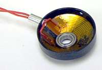
1.2.3. Insert the ball bearing.
Put the ball bearing in the center of the heating element from the inner side of the cone. The bearing rim should contact the heating element (below, left).
1.2.4. Apply the sealing compound to the heater.
Prepare about 1 gramm of the thermoconductive compound Eccobond 285, mixing it with a curing agent in proportion 9:1. The consistency should be like that of a peanut butter. Apply the compound to the bottom side of the heating element (below, right).
1.2.5. Place the heating element into the shield body.
Gently pulling the heater leads and pushing the edge of the heating element, place the element into the shield body. Take care not to deform the element too much. Press it in the shield with fingers only as deep as possible (below, left).
1.2.6. Center the ball bearing relative the shield body hole.
Use a tip of a ball pen or any similar object to center the ball bearing relative the big hole in the heating shield body (below, right). Take care that the bearing rim does not pass through the opening of the heating element!
1.2.7. Press the ball bearing into the hole.
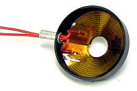
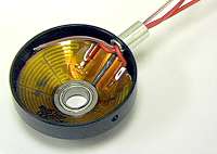
1.2.8. Insert the thermocouple.
Stretch the thermocouple head through the wire guide and shape the leads along the shield wall so that the head is located approximately 90° off from the wire guide. Accurately pull out the heating element leads to remove the loops within the shield body. The result is shown on the picture at the right.
|
|
 |
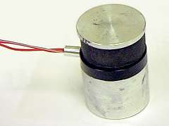
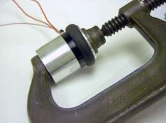
1.2.9. Press the heating element into the shield.
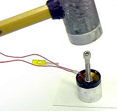
Insert the rubber plug into the shield body. Put the shield on top of the support block. Cover with the pressure plate (below left). Squeeze the whole stack in the clamp so that the plug is noticeably deformed (below right). Leave the whole assembly under pressure for at least 10 minutes.
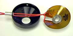
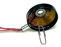
1.2.10. Glue the thermocouple to the shield wall.
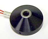
Remove the shield from the clamp. Remove the rubber plug. Using the paper clip fix the thermocouple head against the wall. After pressing the leads will have exactly the shape of the wall. Put a drop of the thermoconductive compound so that it completely covers the thermocouple head. Put another drop between the wire guide and the clip. Put the shield aside as show on the picture until the compound stands completely.
|
|
 |
1.3. Electrical connections.
The wire leads of the heating element are rather short, so at first step you have to elongate them to the desired length (about 3 feet). The thermocouple leads are long, so they have to be shortened to the same length. Then pull all the leads through the heat shrinking tube of an appropriate length. Pull the tip of the tube over the wire guide. After shrinking the tube will be reliably attached to the wire guide. This provides an efficient protection of the wires against breaking at the exit from the wire guide.
Crimp the leads to the connector pins. Mount the connector arranging the pins as follows:
A - heating element |
B - heating element |
C - thermocouple (red) |
D - thermocouple (gray) |
|