|
Remote Access at Non-Cryogenic Conditions and Controlled Humidity
Introduction
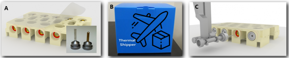
Expanding on the mature remote access program for cryogenically cooled crystals using the SAM System, SSRL now supports remote experiments using crystals at controlled elevated temperature conditions or at controlled humidity and ambient temperature conditions including step-wise Crystal Dehydration Experiments. For these experiments, users ship crystals affixed to magnetic bin bases held inside specialized plates compatible with crystal growth, crystal storage and robotic sample exchange (Fig. 1)
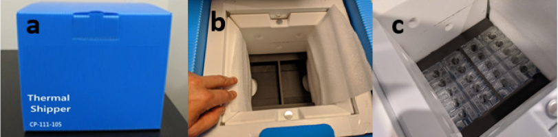
Figure 1. How remote access is accomplished: A) Grow or transfer crystals in a specialized plate; B) Ship crystals to SSRL safely in temperature-controlled containers; C) Mount samples using the SAM robot at the beamline. Controlled humidity and multi-temperature experiments are supported, each requiring different protocols for sample preparation and mounting that depend on the experimental goals:
Supported experimental goals at elevated temperatures include:
In-situ Plate Shipping Kit Components
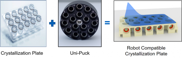
The SSRL In-situ Plate is a combination of a crystallization plate and a uni-puck crystal storage container (Fig. 2). It enables crystallization, transport and remote access mounting of samples on a beamline goniometer at controlled elevated temperature conditions or at controlled humidity and ambient temperature.
Figure 2. The new in-situ shipping plate is a combination of a normal crystallization plate and a uni-puck.. The SSRL In-situ Plate Shipping Kit consists of the supplies needed to grow and ship crystals to SSRL at controlled humidity or to ship crystals sealed in capillaries or other containers for robotic sample mounting at elevated temperatures. The kit consists of the following components:
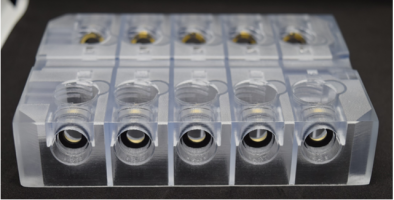
Figure 3. In-Situ Crystallization Plate
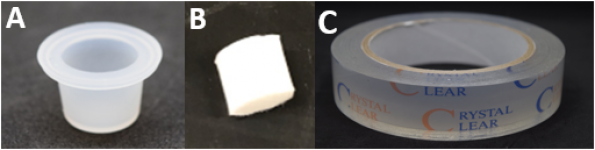
Figure 4. Disposable supplies: A) Silicone cap; B) Absorbent foam insert; and C) Tape for sealing the plates.
Figure 5. Cap and absorbent foam shown inserted into a plate well.
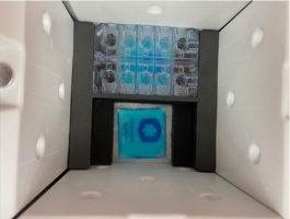
Figure 6. a) Blue Thermal Shipping Container; b) foam inserts are used to stabilize c) the SSRL In-situ Plates.
Plate Inspection and Storage
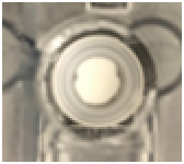
Before each use, the plate should be visually inspected to be sure it is free of dirt and debris (Fig. 7a). Also, inspect the magnetic rings for any signs of corrosion (Fig. 7b). Corrosion can affect the ability of the robot to remove and replace pins. To prevent corrosion of magnets, remove disposable cups containing solutions when plates are not in use. Plates should be stored dry.
Figure 7: a): All 10 ports of the plate should be inspected before use. b) Any debris should be removed and any corroded magnets (see red arrow) should be replaced. Magnets should have a consistent shiny gold or silver coating with no visible scratches or dark areas Note: when the plates are not being used, remove all tape, dry the plates and store then in a dry dark area. Plates left in sunlight or under fluorescent lights may turn yellow with age. The yellow plates are still OK to use, but less light will transmit through the plate when viewing the samples through a microscope.
Sample Pin Base Selection and Compatibility
The SSRL in-situ crystallization plate is compatible with a variety of sample holders (meshes, chips, capillaries, grids, etc.) affixed to magnetic sample pins (Fig. 8). It is important to choose magnetic bases that are compatible with the Stanford Automated Mounter robot (SAM). Detailed instructions about the allowed sample bases for use with the SAM robot can be found in the SAM Manual, including a size chart for sample pin length and details about sample pin vendors and part numbers.
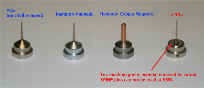
Figure 8. Types of sample pin holders that can be used with crystallization plates. Note: The SAM system supports only Hampton-style CrystalCap Copper Magnetic pins or CrystalCap Magnetic pins. SPINE pin bases are not allowed because they will cause damage to the SAM robotic system.
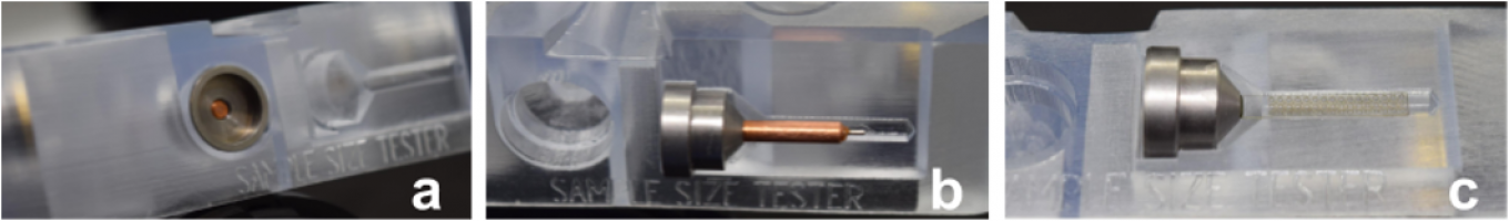
Sample Pin Assembly - Length and Width Size Limits
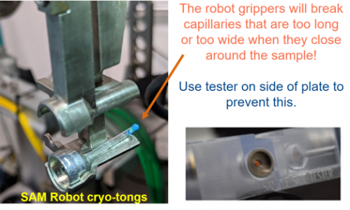
Critical: It is imperative to use the proper length and width samples to ensure reliable operation with the SAM robot. Otherwise, the robot grippers may crush and damage samples. Fig. 9 shows a capillary that is too long, placed inside SAM robot grippers (i.e. cryo-tongs). When the robot grippers close, this capillary will be crushed (but it would be OK if the capillary was 1 mm shorter). Note: To make testing the sample pin size easy, a pin tester has been incorporated into every SSRL In-situ Plate.
Figure 9. Example of a sample pin setup that is too long for the robot gripper. The tester on the side of the plate can be used to test pin compatibility. The pin tester consists of a cavity and a side pocket (Fig. 10a) where sample pins can be tested. If the pin fits inside the cavity with the back of the pin flush to the surface of the plate (not sticking out past the surface of the plate material), then it should fit well inside the SAM robot cryo-tong/gripper. If the sample pin does not properly fit inside the cavity, a side cutout (Fig. 10b and 10c) helps with inspection of the assembly to locate the parts that are too large.
Figure 10. a) The cavity and side pocket testing area on the SSRL In-situ Plate. The back of the pin should be flush with the plate surface when inserted into the testing port. b) The side cutout can help identify features that are too large if the pin base sticks out past the plate material. c) Grid mounts should fit in the groove both lengthwise and widthwise. Bottom-line, if the sample pin assembly has a solid base and properly fits inside the SSRL In-situ Plate testing ports, it can be mounted by the SAM robot for remote data collection. This provides flexibility in the types of samples that users can ship at ambient temperatures and the types of experiments that can be supported on the SSRL beamlines.
Controlled Temperature Experiments
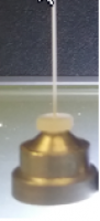
Remote room temperature and multi-temperature experiments are possible by shipping samples in appropriately sized sealed capillaries or microfluidic chips (see above for Proper Dimensions). For example, Fig. 11 shows crystals inside a sealed thin capillary that can be mounted remotely from plates. See the following section for Instructions on the Use of MiTeGen Sleeves or Capillaries.
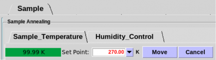
Figure 11. Example of a thin capillary mount compatible with the SSRL In-situ plates. The Oxford Cryo-cooler system used at most SSRL beamlines can operate at a temperature range between 100 K and 370 K. Normal operation is at 100 K with no user adjustments enabled. However, if you send sealed samples in the SSRL In-situ Plates, you can ask your user-support scientist to enable remote adjustment of the temperature from the Blu-ice control software Sample Tab (Fig. 12).
Figure 12. Sample Tab in the Blu-Ice GUI with the Temperature sub-Tab. The green area displays the current sample temperature. To change the set point temperature, type a value in the entry box (which will be in red text) then click “Move” to change in set point (the “set point” text will then turn black).
Use of MiTeGen Sleeves or Capillaries
A popular method to ship samples at room temperature is in MiTeGen sleeves or capillaries. Note: If sleeves or capillaries are used with plates, the instructions are different from the standard methods. Instructions for using sleeves or capillaries:
Critical: If the capillaries or sample holders in sleeves are too long, they will be crushed by the sample mounting robot (see Fig. 9 above)
Critical: Do not use grease or wax of any kind. Grease and wax will interfere with robot operation.
Note: To prevent crystal slippage when using sleeves, a key step is using a loop that is appropriately sized to hold the crystal so it doesn't have anywhere to go. The use of MiTeGen "Microgrippers" or meshes with excess solution wicked away can be helpful as well.
Note: While MiTeGen sleeves and most polymer capillaries are not watertight, glass or quartz capillaries properly sealed with epoxy are watertight and do not require any additional solutions to be added in the plate chamber.
Multiple crystal types have been shipped in plates using MiTeGen sleeves and glass capillaries for remote collection, often producing diffraction data between 1.5 and 1 Å resolution.
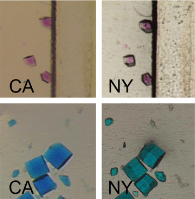
Controlled Humidity Experiment
Figure 13. Crystals in windowed grids inside plates shipped between California and New York.
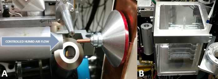
Important: Schedule with user-support a week in advance to ensure the Arinax humidity nozzle is in place for your experiment.
Figure 14. A) Humidity control of the sample; B) Humidity-controlled sample staging area.
Figure 15. Humidity Control sub-Tab in the Blu-Ice Sample Tab.
Recommendation: Although instructions are online, it is recommended to work closely with your assigned beam time support staff during your first controlled dehydration experiment.
Growing or Transferring Crystals Inside Plates
The SSRL In-situ Plate can be used to grow crystals by hanging or sitting drop vapor diffusion on Grids or other substrates affixed to magnetic bases. Alternatively, crystals grown elsewhere can be transferred onto substrates stored in charged plates. Note: Plates can be reused for multiple crystallization trials and trips to the synchrotron. The steps below cover both in-situ growth and sample transfer scenarios.
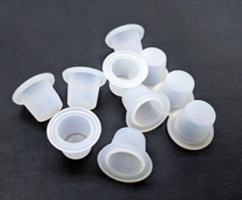
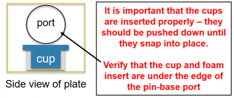
Figure 16. Disposable silicon cups. Following the instructions below, carefully install the cups to avoid problems with solutions spilling or collisions with the SAM robot:
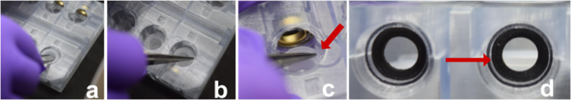
Figure 17. a) & b) Steps for inserting the silicon cup into the SSRL In-situ Plate. c) The cup edge is being inserted under the well ledge (see red arrow). d) The cup should not protrude above the silicone o-ring. Critical: If the cup is not properly inserted, it may interfere with insertion of the magnetic pin base.
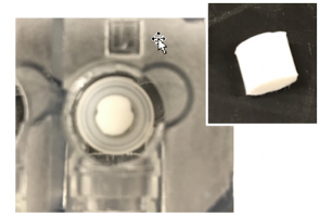
Note: An option to ensure the foam is fully saturated, is to add excess liquid into the cup and then after a minute remove any excess liquid above the foam that has not been absorbed with a pipette.
Figure 18. The foam insert placed inside a silicone cup. Note: Adding 0.6% agarose to the well solution is an alternative approach to avoid spilling, if the absorbent foam inserts are not available. A video is available for detailed instructions on this process.
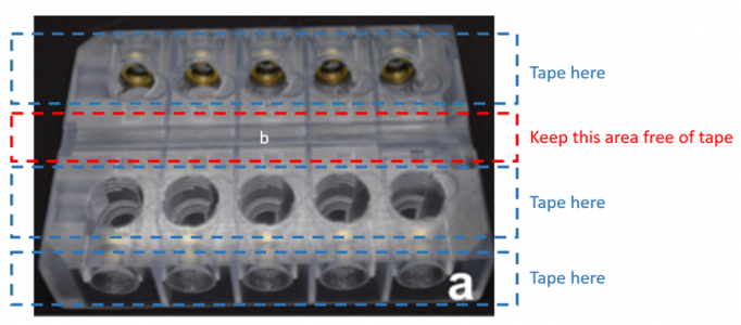
Figure 19. Area on the plate to avoid applying tape.
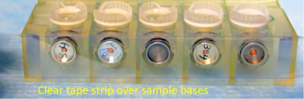
Figure 20. Sample pins are secured with a strip of tape.
Shipping Samples in SSRL In-situ Plates
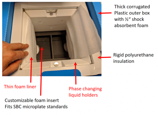
Up to 6 SSRL In-situ Plates can be safely transported in one Blue Thermal Shipping Container. The thermal shipper consists of many layers of material optimized for maintaining a constant temperature and for reducing physical shock to samples inside (Fig. 21).
Figure 21. Blue Thermal Shipping Container is built to safely ship samples at ambient temperature to SSRL. The thermal shipper will maintain a temperature of between 15 and 25 ᵒC for 7 days. Additional gel packs within the shipper will further stabilize the temperature. Follow these steps to ship plates to SSRL in the thermal shipper.
The form will produce a shipping label to tape on the outside of your shipping box and a required return shipping form that should go inside the shipping box just under the polyurethane lid.
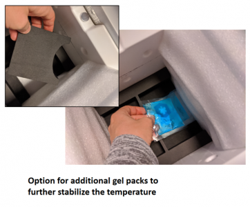
Caution: Make sure not to pierce the aluminum covers of the liquid filled chambers.
Figure 22. Additional gel packs can be added to further stabilize the temperature.
The Blu-ice Experimental Control Software Interface
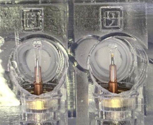
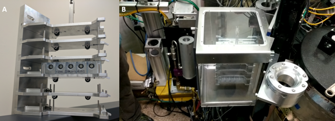
A specialized enclosed shelf can hold up to 5 plates (Fig. 24A) that is in reach of the SAM robot at the beamline. The shelf is enclosed inside a Plexiglas box (Fig 24B). The environment in this box can be maintained at a specified temperature and humidity.
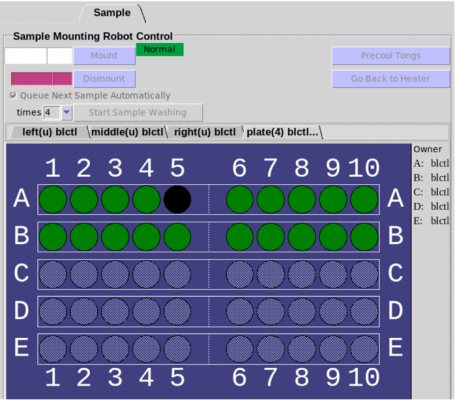
Figure 24. A) Specialized shelf that houses the plates B) The shelf resides in a temperature- and humidity-controlled tank at the beamline. A simple interface has been incorporated into the Blu-Ice Sample Tab to mount samples from the SSRL In-situ Plates located in the shelf (Fig. 25). Each position of the shelf is labeled A-E in the software with the top shelf labeled as “A”. Each plate holds ten samples – numbered 1-10 in the software interface.
Figure 25. Blu-Ice tab Sample Tab for mounting samples from SSRL In-situ Plates. To mount a sample, select Plates from the sub-tab of this interface. Click on the desired sample pins to mount (samples that are OK to mount are highlighted in green) and then click the Mount Button. Samples can only be mounted from plates that have been assigned to your account. |