Sample Mounting Grids
Table of Contents
These sample grids were developed at SLAC for automated data collection from a large number of crystals. Each grid can hold up to 75 crystals in known locations, enabling automated positioning in the X-ray beam and reducing the total number of sample pin mounting cycles required to obtain a complete multi-crystal dataset. The grids are designed for experiments where only one X-ray exposure is collected from each crystal or only a small rotation range is used to collect data (typically +/- 5 degrees).
The grid is compatible with most automated sample mounting robots. The grid's outer dimensions are the largest area that can reliably fit inside the port of a SSRL cassette and the Stanford Automated Mounter (SAM) robot grippers. A comparison of the form factor of a grid assembly and a standard Hampton copper-magnetic pin assembly is shown below. For automated positioning of samples into the X-ray beam, the locations of each hole in the grid that contains a crystal is saved in an excel spreadsheet.
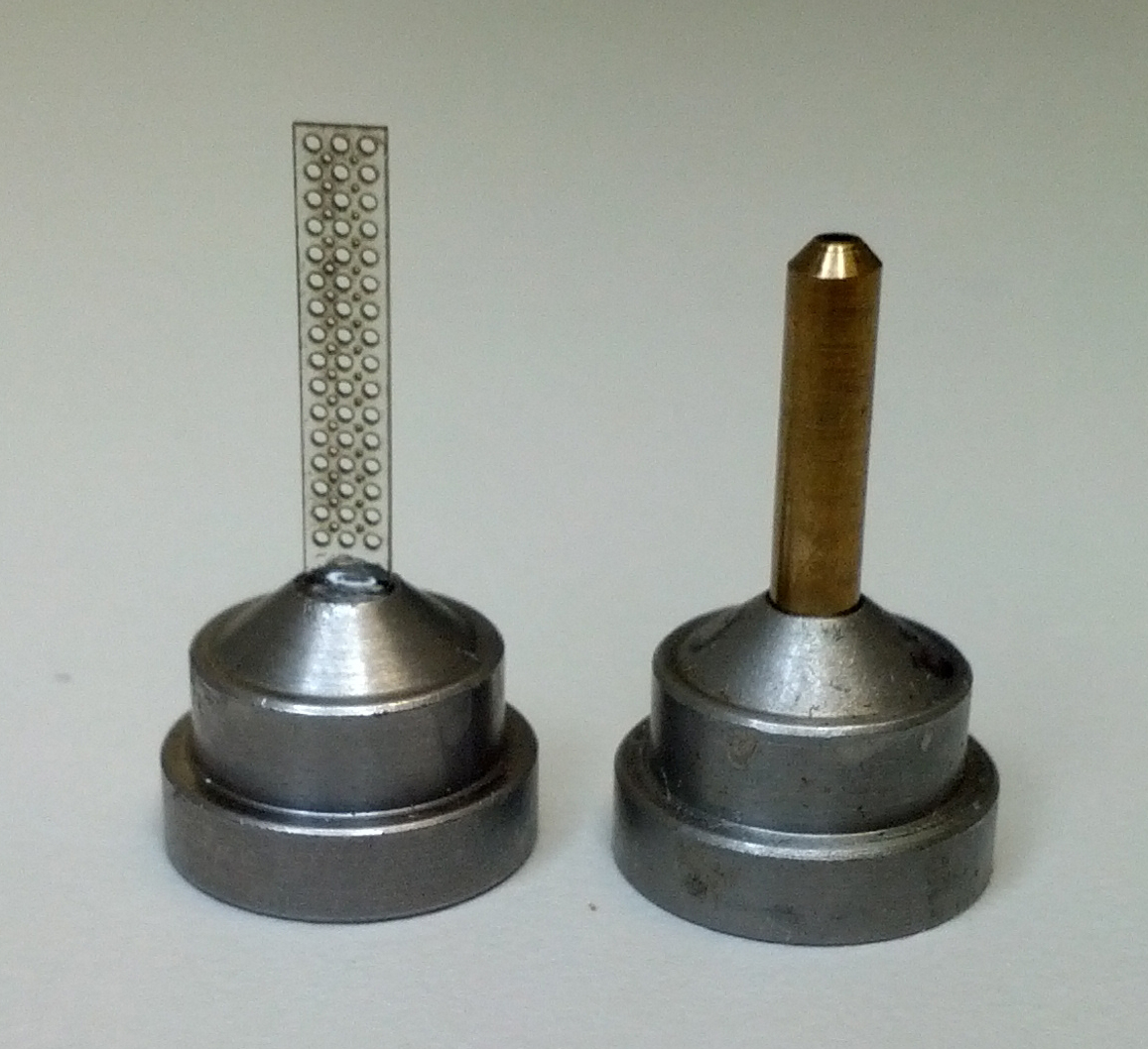
Comparison of Grid Assembly to Hampton copper-magnetic pin assembly
Sample grids are made of 200 micron thick polycarbonate with laser-etched rows of holes that are 400µm, 200µm, or 125µm diameter. The schematic below shows the hole layout and overall grid dimensions.
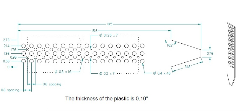
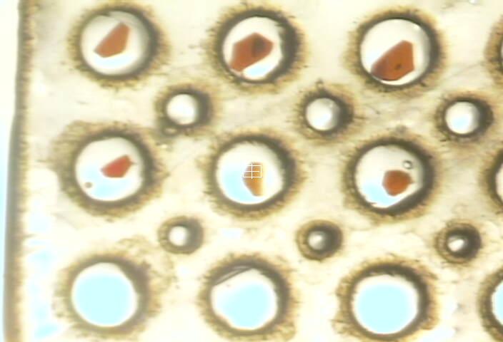
- During data collection the center of each grid hole (or port) containing crystals is centered into the X-ray beam. Therefore it is important to match the grid hole size to the crystal size so the crystal will be in the middle of the grid hole and hit by the X-ray beam.
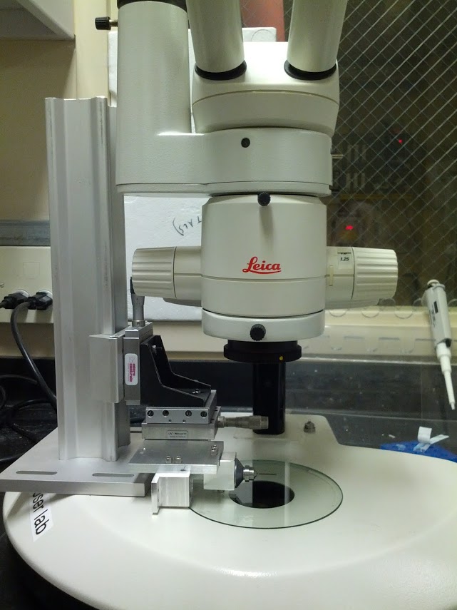
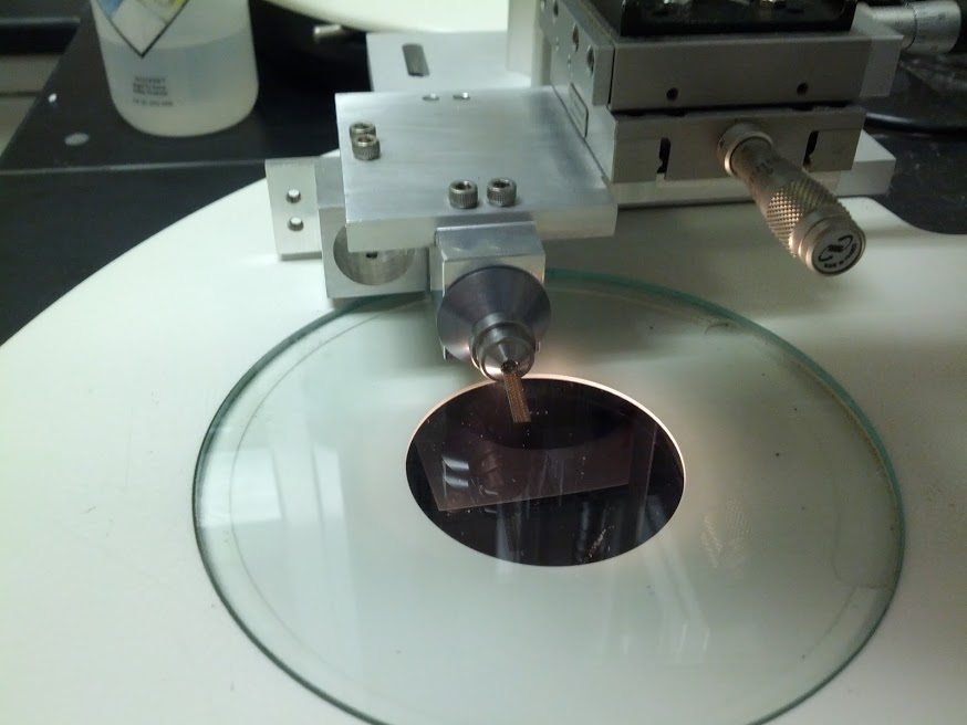
- To mount samples in grids, please mount your grid/pin assembly on a magnetic holder under the microscope as in the figures below. It is best to use two microscopes, one to view crystallization trays and one to view the grid. If only one microscope is available, it is helpful if the grid is held at the same height as the drops in the crystal trays so you do not need to refocus the microscope during transfer.
A helpful lab bench setup for grid loading includes a long working distance microscope and a magnetic holder for the grid base.
- To prevent the crystals from drying out, pre-fill each hole inside the grid with a cryo-protectant oil such as paratone-N or paraffin. Use just enough oil so that a film of oil is across each hole but avoid excess oil on the grid surface. One approach is to use a fine needle to apply the oil and then scrape off the excess oil with the side of the needle until the grid surface appears "dry".
- After applying the oil, inspect the grid. If a hole doesn't have enough oil, a film will not hold. Add oil to holes that have no film and re-scrape the surface. Avoid bubbles. Clean out a hole with bubbles and reapply cryo-protectant if necessary. An even film is critical to hold the crystal in place in the center of the hole rather than it sticking to the side of the hole.
- Hampton cryo-loops may be used as a hand tool to transfer the crystals from the crystallization tray into a grid hole. It is convenient to match the cryo-loop sizes to the hole sizes in the grid. The use of matching cryo-loops to pickup crystals makes it easier to determine which size hole in the grid best matches the crystal size and makes it easier to transfer the crystal from the loop into the grid hole. We found the 20µm cryo-loops in the 0.05 mm - 0.1 mm, 0.1 mm - 0.2 mm, and 0.2 mm - 0.3 mm size ranges worked best.
- Before transfer into the grid, each crystal should be transferred from the crystallization drop into a drop of paratone-N (or other oil). The loop tool should then be used to gently move the mother liquor away from the crystal surface and ensure a good coating of oil.
- Once properly coated with oil, the crystal is pulled out of the drop, wicked to remove any excess oil, and placed in the center of the smallest grid hole that will accommodate it.
- As you load the grid, watch to ensure the crystals do not sit in the hole at a preferred orientation (such as the largest face always parallel to the grid surface). If there is a preferrential orientation, use a cryo-loop to tilt the crystals in the hole by varying amounts.
- Load the columns on the top portion of the grid first.
- Once a suitable amount of grid holes are filled with crystals, the grid is placed on a magnetic cryo-wand and flash frozen by plunging in liquid nitrogen.
- The grids may then be inserted into an SSRL cassette or uni-puck (directions here) for automated sample mounting at the beamline.
- Each grid likely has far more holes than can be filled with crystals in practical amount of time. The time you should take in mounting each grid is determined by the robustness of your crystals in the oil used. The oil prevents the crystals from drying out too quickly but may also damage the crystal over time.
- Tests need to be done on your particular samples to determine how many crystals can be loaded before flash freezing the grid. Ideally this should be done by 1) filling each the grid hole with well diffracting crystals (following the steps outlined above) while recording the time each crystal was inserted and 2) collecting diffraction data from each crystal. For myoglobin crystals, we could leave the crystals in paratone-N for 10 minutes before they were damaged but other crystals are more sensitive.
- Mount a crystal in a traditional cryo-loop from the same drop to ensure that the crystals in the drop diffract well. This will ensure grid mounting times determined from the procedures above are not skewed due to poor crystal quality.
- At the start of grid loading, a timer may be set to alarm when the grid should be flash-frozen.
- Crystal positions as well as any notes should be recorded into an Excel spreadsheet with a specific format. This format is readable by our data collection software.
- The grid holes are numbered in a specific format depicted below.
- Click here to download a template excel spreadsheet. Make sure that your grid orientation is correct (and not flipped 180 degrees). The images below show an example of how this spreadsheet should be filled out.
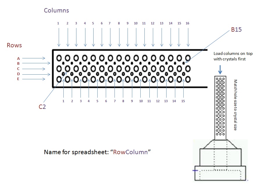
The naming convention used to store grid port locations in the excel spreadsheet
Grid Assembly
The loose grids [Figure A] are affixed into the stainless steel portion of a Hampton copper-magnetic pin base [Figure B] using epoxy. The stainless steel base may be obtained by unscrewing a copper post from a Hampton copper-magnetic pin assembly. They are also available for purchase from Crystal Positioning Systems as item number CP-111-014N.
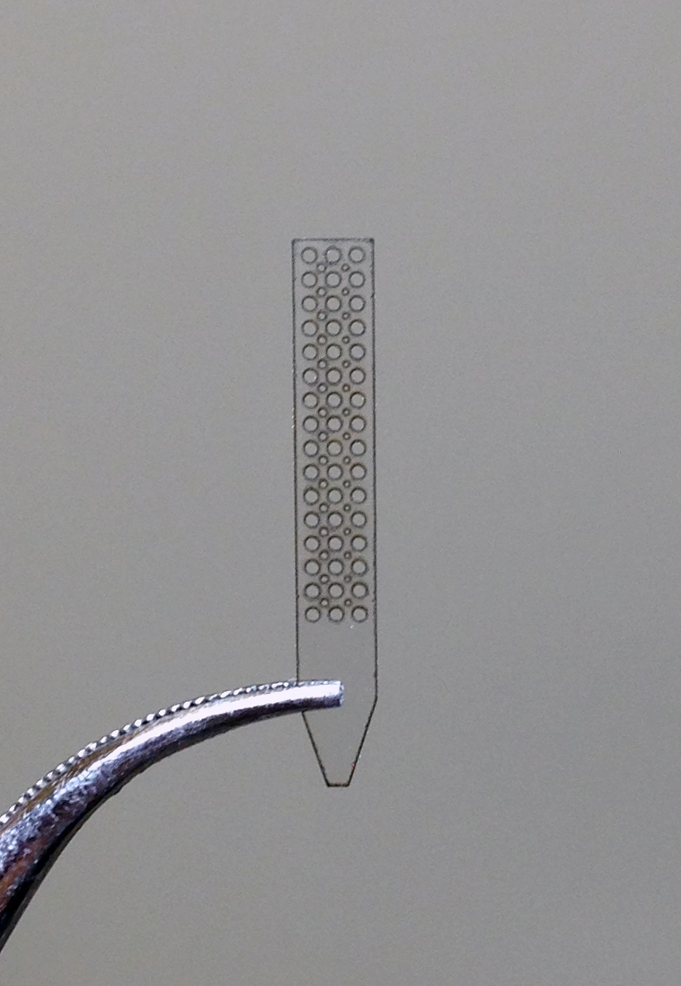
Figure A
|
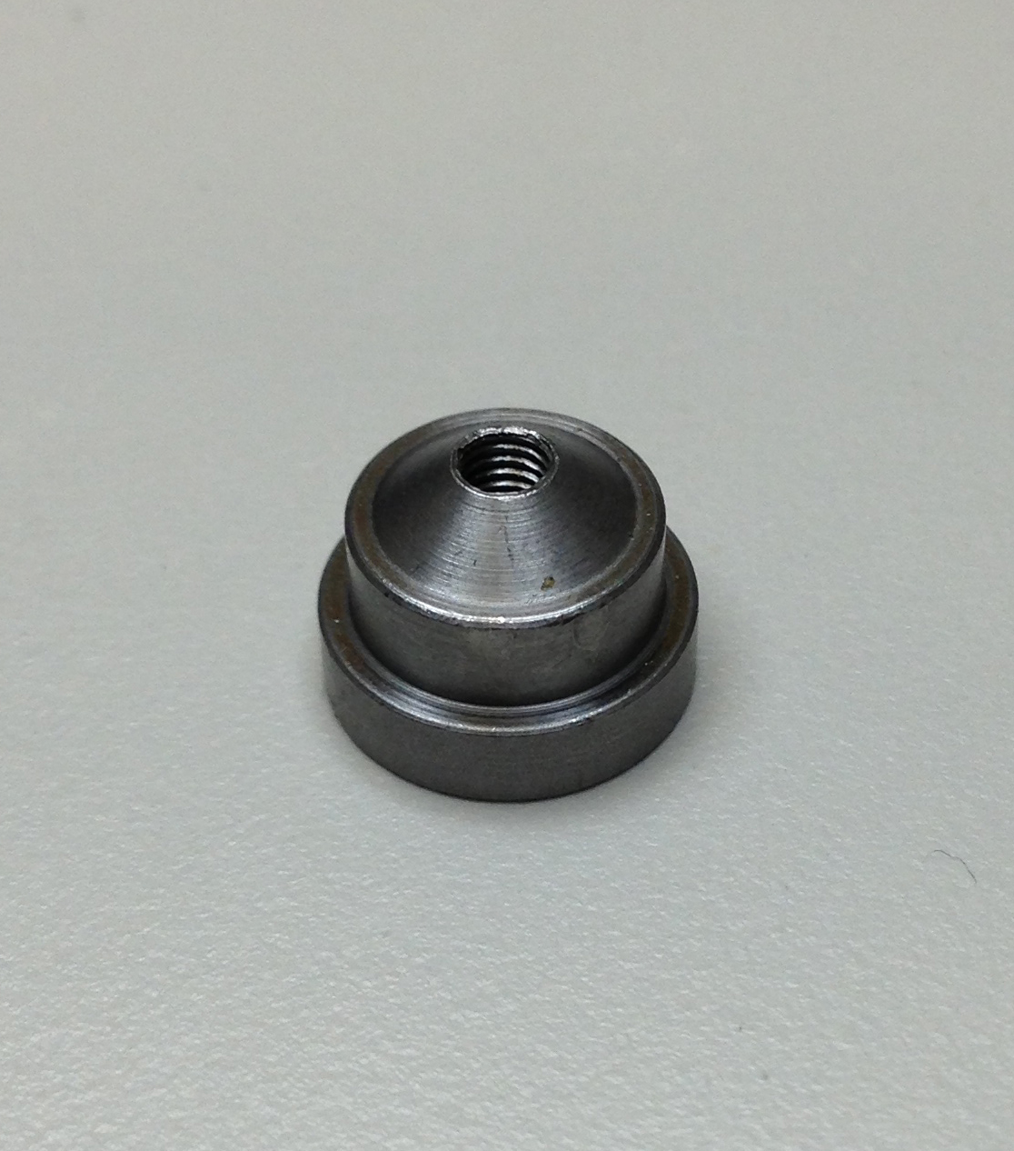
Figure B
|
- Set the grids in the pin base such that the tapered part of the grid is well below the top of the pin.
- Make sure the grids are straight. Don’t allow epoxy to get into the grid holes, especially the lower rows closest to the pin base.
- We use a jig to help keep the grids straight while the epoxy sets, as shown below.
- After the epoxy sets, test grids to ensure that they are firmly in place.
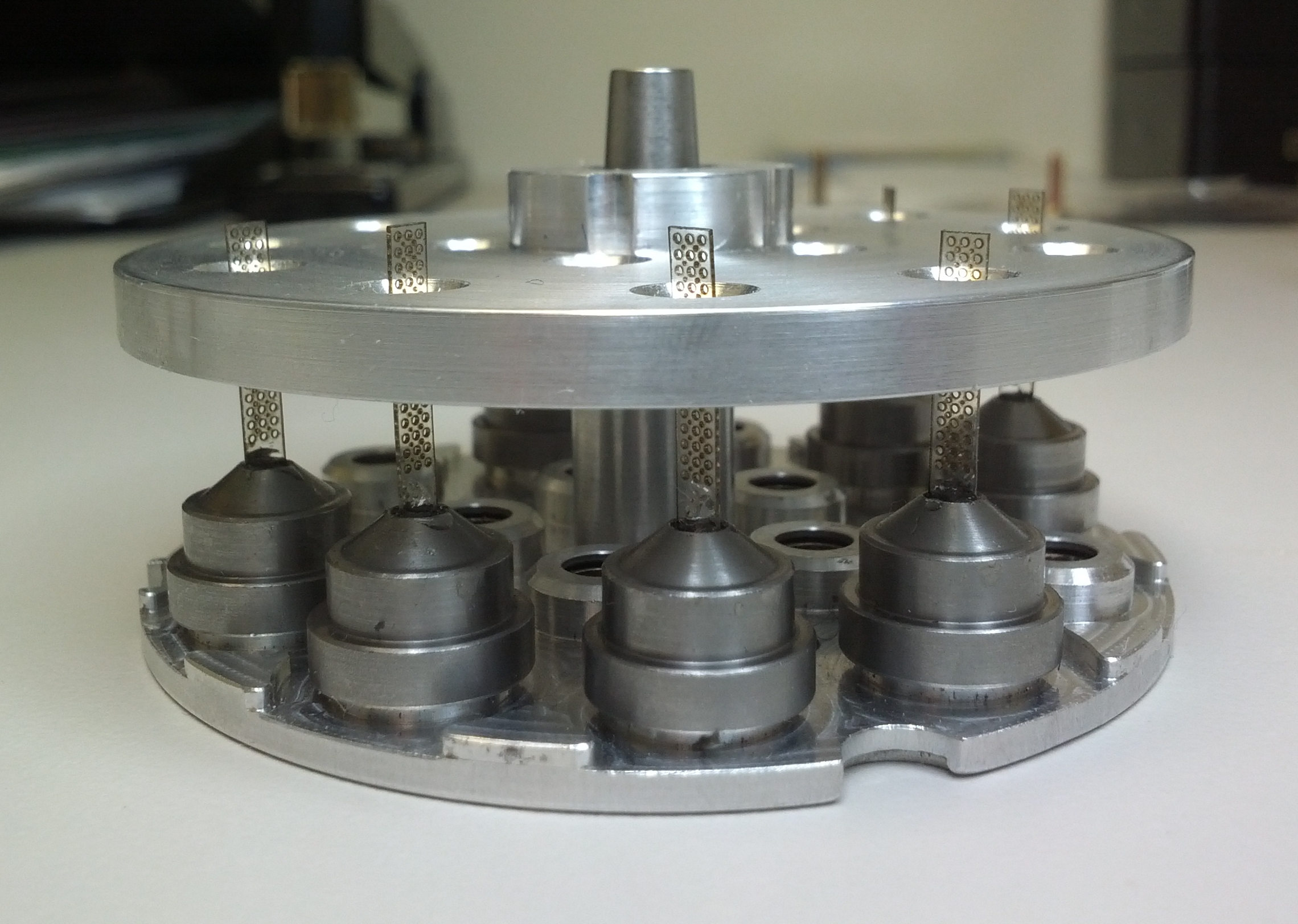
The jig prevents the grids from tilting as the epoxy sets. The jig consists of two parts: 1) the bottom half is the base piece of a standard uni-puck and 2) a specialized cover machined from aluminum (download the schematic here).
Back to main hardware page
|