A Quick XDS Tutorial for SSRL
Table of Contents:
Back to Software Facilities Page
Introduction
X-ray Detector Software (XDS) processes single-crystal diffraction data. This site provides details necessary to run XDS at SSRL. Detailed program documentation is available online. Use of XDS is also incorporated into the automated processing pipeline used at SSRL.
The XDS package can process diffraction images collected with various types of detectors. There are two ways to use the program package at SSRL, either (A) using the autoxds script developed at SSRL (recommended!) or (B) launching the XDSGUI application which is available at the SSRL-PX computing cluster. It is also possible to copy and edit detector-specific input files (.INP); however, both the autoxds script and the XDSGUI application will generate input files that can be edited and re-run by the user (see below); autoxds generates the .INP files automatically.
Using the autoxds script
- You do not necessarily need to create a subdirectory if you would like to have the XDS output collected in one directory - the
autoxds script will do this for you. You can either move to the
directory where you have collected your images or a different
directory of your choosing.
- Run autoxds. You must supply the first image in the data set as
input - e.g. autoxds thau_c3_1_1_001.img. The script will extract all the required information to run XDS
from the image header and generate and run the input scripts for
XDS and XSCALE. Note that the input script can be edited and run "manually"
as explained in the sections below.
- By default, the script will attempt to autoindex, integrate and
scale all the images sharing the same root name as the input file. If
you want to restrict the number of processed images, supply the number
of the last image. For instance, to process images 1 to 90 in the
previous example, type:
autoxds thau_c3_1_1_001.img -last 90.
- Type
autoxds -help to obtain a list of other
options.
-last    followed by last image to be processed. Defaults to last image in directory
-full    Reprocesses the data using the refined parameters from the CORRECT step
-symm    followed by space group *number*. NOTE: This option is only used if the unit cell is supplied.
         If the cell is given, the space group will be used for indexing and integration. The space
         group will *not* be changed by POINTLESS.
-cell    followed by a b c alpha beta gamma
-highres followed by high resolution limit. Defaults to no limit
-lowres  followed by low resolution limit. Defaults to  40 A
-isigma  followed by I/SigmaI cutoff.
-friedel followed by  true (default) or false (for anomalous data)
-merge   followed by true (default) or false (output unmerged reflections). NOTE: this
         option only has an effect if you use the XDSCONV script to transform to SHELX/CNS format
-scala   uses scala for scaling and merging reflections instead of aimless (default since Sep 2013)
-wait    followed by the number of seconds to wait for the next image in the data set. Defaults to the exposure time plus 10 seconds
- Note that XDS does not run multiple jobs in paralell if you use
the -wait option. Therefore this option should only be used
when processing is started while data are still being collected and
in conjuntion with the -last option: if the last image number in the
data set is not specified, the program will not wait for new images,
only process the images written to disk when the script is started.
- After running XDS and scaling the data with XSCALE (part of the XDS
package), the script will also run POINTLESS on the integrated intensity
file output by XDS. POINTLESS will determine the correct space
group and output and mtz file suitable for input to the MAD
scripts, unless a space group *and* a unit cell have been
supplied. In this instance, POINTLESS will merely copy the space group
from XDS (this is useful to force choice of the correct
enantiomorph or when the data is very incomplete, as can be the case
in a multicrystal experiment). Finally, the script runs AIMLESS (default) or SCALA
(optional) to scale and merge the
reflections and TRUNCATE to convert the intensities to amplitudes.
- If you specify a I/SigmaI cutoff, the script will re-run
AIMLESS or SCALA twice: the first time it will determine at which resolution the
mean I/sigmaI falls below the specified value, and the second time it
will apply this cutoff to the scaling. The resolution cutoff will also
be applied by TRUNCATE, so the output mtz will not contain data to
higher resolution.
- If you have low resolution data, use an appropriate
highres cutoff; this will get applied at the indexing and data
integration stage, which may improve the results.
- The script also generates an XDSCONV input script to transform the
reflections into a format suitable for input to CNS or SHELX.
Output
The output files from autoxds are stored in the
subdirectory ''imagename_xds''. The file ''imagename_xds.log''
contains the logs for the XDS package programs (XDS and
XSCALE). For information about the XDS output files, see the section below.
The script also writes out writes the command file/input file for each program it
runs. This facilitates manually rerunning these programs with different
parameters or input. To re-run XDS or XSCALE, simply type xds (or
xds_par) or xscale in the same directory as the input files. To re-run
the POINTLESS, AIMLESS/SCALA and TRUNCATE programs, use the ''source'' command
as in the following example:
source aimless.com
The files ''imagename_pointless.log'' ,''imagename_aimless.log'', ''imagename_scala.log'',
''imagename_truncate.log'' are the logs for POINTLESS, AIMLESS, SCALA and
TRUNCATE respectively. The file ''imagename_truncate.mtz'' contains the
merged structure factor amplitudes in mtz format that can be used for subsequent
structure solution. For more information, see the CCP4 documentation
If you wish to obtain an output file for input to CNS or SHELX, edit
the XDSCONV.INP file in the results directory. Edit the line
"OUTPUT_FILE= XDS_CONV.HKL CCP4_F". Replace CCP4_F with CNS or SHELX.
Save the file, and type ''xdsconv'' in the same directory.
If you want to use the solve_structure.com script for structure
solution, use the file ''imagename_xds.mtz'' (output from POINTLESS)
as input. Note! If you have a MAD data set, you may want to
ensure that the data for all the energies are indexed
consistently. You can do this with pointless, as in this example:
pointless hklref image_E1_xds.mtz hklin image_E2_xds.mtz hklout image_E2_reidx.mtz
In this example, the output file image_E2_reidx.mtz will be
reindexed using the same scheme as image_E1_xds.mtz.
Merging data from multiple crystals
A script called multiscale can be used to merge multiple data sets
processed independently, collected either from the same or different
crystals. The script has been written specifically to deal easily
with the output from autoxds. The script reads in the integrated
intensity mtz files from POINTLESS and after verifying that the space
group is the same for all data files, it reruns POINTLESS to ensure
consistent indexing and combine all the data into a single mtz file
which will then be further processed with AIMLESS and TRUNCATE. The
script can also be optionally used to analyze the isomorphism of the
data sets by using the program BLEND.
- The multiscale script is run from the command line,
by typing
multiscale [options]. By default, the script
will find files of the form name_xds/name_xds.mtz in the same
directory where the script is run, and combine all the files with the
same space group in the header as the first one. A list of other options
available can be obtained by typing multiscale
-help.
-dir      followed by the directory where the xds processing directories generated by xds are
-mergedir followed by directory where multiscaling results will be stored
-symm     followed by space group *number*. If the spacegroup in the mtz header of a data set matches, the data will be used for merging.
-highres  followed by high resolution limit in A. Defaults to no limit
-isigma   followed by I/SigmaI cutoff.
-friedel  followed by  true (default) or false (for anomalous data).
-data     followed by an individual xds processing directory. It can used as many times as there are directories.
-iso      followed by the maximum percentage linear cell variation tolerable. If this option is used, the program BLEND will be used to
          analyze and combine the data.
Both a full or a relative path can be used to
specify the dir name. If you want to select only some of the autoxds processing subdirectories
in a directory or if they are located in different directories, use
the option -data; you must provide a -data keyword for each
directory. For example:multiscale -data ../test_1_xds -data
../test_2_xds -data ../test_3_xds. Currently it is not possible to provide the name of the
mtz file directly.
The mergedir directory is called "merge" by
default. The program will overwrite the mergedir generated in a
previous run if they are given the same name, but it will create a
backup copy in the directory "mergedir"_old; older backup directories,
will be deleted.
The reference space group will be extracted from
the header of the mtz multirecord file in the first autoxds processing
subdirectory in the list. This can be a problem is this mtz file
happens to have the wrong space group. If this happens, make sure that
you reprocess the data with autoxds providing both the correct symmetry
and target cell as input as described in above; if the crystals are non-isomorphous
to the extent that it is impossible to index and
process of the data sets in the same space group, use the option
-symm to specify which one should be selected.
Use the -iso option, followed by the maximum
unit cell variation to run BLEND. A unit cell variation of 1% (iso 1.0) is a a good starting ballpark value for the maximum tolerance,
although the optimal value will depend on the data resolution and the
nature of the non-isomorphism. BLEND will be run once in analysis mode,
to produce a dendogram and cluster statistics and then in synthesis
mode to scale and merge all the clusters with a linear cell variation
less than the specified.Note 1: BLEND does not work with data
sets with gaps in the oscillation (for example, a SAD data set
containing an inverse beam pass).Note 2: The "highres", "isigma"
and "friedel" options have no effect in conjunction with "iso".
If both highres and isigma options are used,
the lowest resolution cutoff will be applied. For example, if highres
= 3.0 and the Mn(I)/sd value falls below the given isigma at 2.5 A,
the maximum resolution will be determined by highres, and viceversa.
Troubleshooting
- Note that before October 2012 the script used to check the header
of the images to search for gaps in the rotation. As XDS and the
scaling programs
automatically handle those this function has been commented out. However,
XDS will still fail if the numbering of the images is not consistent
with the gap in oscillation (this should not be the case for
data collected at SSRL); if this is an issue, the data must be processed in
parts and then merged together with POINTLESS or a similar program
before scaling them.
- Occasionally the xds indexing fails. The script will print the
following output:
Autoindex failed. See thau_c3_1_1_xds/IDXREF.LP
It is possible that XDS has found the autoindexing
solution, which however fails the program's stringent
criteria. Because this happens relatively frequently, the script will
keep on integrating assuming that the solution is correct.
You can determine if this is the case this by looking at the end of file "IDXREF.LP" to get a listing of the
possible indexing solutions. An example of the listing in the IDXREF.LP file is given below.
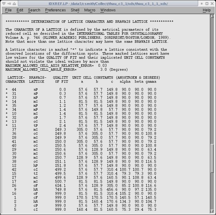
The asterisk on the left side indicates the possible choices of the unit cell and a "QUALITY OF FIT" is given for each possibility.
The correct cell is typically the last of the asterisked solutions.
- If the autoindexing appears to be incorrect, you may need to use
more images. Refer to the autoindexing
troubleshooting section below. You can also try supplying the
correct unit cell from the command line. Example:
autoxds ../LARGECELL/d99n-c4_1_0001.cbf -cell 63.87 63.87 505.36 90 90 120 -symm 177
Note1 If you do not supply the space group with the cell, the
program will integrate in P1. If you supply the space group, but not
the cell, XDS will not use the space group for autoindexing, and POINTLESS will re-determine the input space group before
running AIMLESS or SCALA to scale and merge the data. However, XSCALE will scale
the date using the input space group.
- If you try to force a symmetry and the data integration
works but the scaling fails, try running the script without
specifying the symmetry. If this is not possible, edit the
pointless.com script and rerun it after removing the "-c"option.
- If the scaling statistics after scaling are poor, try
rerunning the
script using the full option. This will reintegrate the data
using the refined orientation and symmetry parameters from the
CORRECT step. For example:
autoxds ../LARGECELL/d99n-c4_1_0001.cbf -full
- In some difficult cases, it may be required to open the input file
XDS.INP and tweak the input parameters for
XDS. You also need to edit the oscillation axis orientation if you
collect data on phi in conjunction with a kappa
offset. After editing the input, rerun XDS and all the subsequent
programs as indicated in the previous section.
Using the detector-specific .INP files
SSRL provides the detector specific input files and the user needs to make very
few changes. Since the indexing and integrating process is slow, it may be better to start the XDS job after the data
collection. We have seen advantages in using XDS for the processing of poor quality diffraction images.
We need to run three programs xds, xscale, and xdsconv to get the final reflection file to the user specified
format. xds performs autoindexing and integration, xscale is for merging and scaling, and xdsconv for
converting the reflection files to the user specified formats.
The XDS package also provides a program, VIEW, for visualizing diffraction images as well as control images produced by
the "XDS" package.
Indexing and Integration
The XDS program can be started from any of the data processing machines by typing xds (Program name "xds" is case sensitive).
The following steps are required to run "xds". The "Files" section of the online documentation provides details of all the input and output files.
- Create a subdirectory if you would like to have the XDS output collected in one directory. Move to the directory where you would like to run XDS.
- Make a symbolic link to the diffraction data image directory using "ln -s path_to_image_directory images" command. Or you could just store the image files in an "images" directory under the XDS processing directory.
- Copy the detector specific input files (eg., XDS_Q315.INP) from the template directory (/data/user_login_name/templates/xds). Rename this file as XDS.INP (Note: This is case sensitive and please use upper case for the name).
- Go to the "User Input" section of the XDS input file and input values for your specific experiments given below. Please note that these values are at different locations in the XDS input file provided with the XDS package. The "keywords" have to be in upper case.
-
Beam Center represented by ORGX and ORGY keywords. Unlike XDS and
mosflm programs, XDS requires the beam center values in pixels. To
get the pixel value divide the current beam center values (mm) by
the "PIXEL_SIZE" from the image header (The image header can be
displayed in WebIce). If the detector is offset, please consult
the Users'
Guide for help.
- DETECTOR_DISTANCE (mm).
- OSCILLATION_RANGE or delta_phi (degrees).
- X-RAY_WAVELENGTH (Angstrom)
Values for the above three parameters are in the image header.
- SPACE_GROUP_NUMBER (xds uses only space group numbers. Change it to "0" for auto indexing.
- UNIT_CELL_CONSTANTS (if the SPACE_GROUP_NUMBER is known).
- NAME_TEMPLATE_OF_DATA_FRAMES (eg., ./images/myoWI3_1_???.img. The ADSC CCD-detector image data format is SMV). XDS package can't read lines longer than 80 characters. Therefore, use link statement (ln -s) to specify long path names.
- DATA_RANGE (number of frames. eg., 1 200)
- SPOT_RANGE (This specifies the range of images for finding spots for auto indexing. Spots from multiple ranges (up to 10) could be selected by inserting additional "SPOT_RANGE" commands. The default mode uses images specified in the "DATA RANGE".)
- FRIEDEL'S_LAW=FALSE !Default is TRUE (The "FRIEDEL'S_LAW" should be "FALSE" to generate a strategy to maximize Bijvoet reflection pairs (this is important for anomalous data collection).
- JOB (where you tell the program to what to do. The various keywords are XYCORR (calculates lookup tables of spatial corrections for each detector pixel), INIT (determines three lookup tables required for the processing steps), COLSPOT (locates strong spots and saves their centroids), IDXREF (perform indexing using the parameters in XDS.INP file and the centroids of the spots), DEFPIX (detects masked regions or untrusted pixels), XPLAN (for running strategy), INTEGRATE (determines the intensity of each reflection), and CORRECT (accepts good reflections from the integrated .HKL file). The default mode runs all of the programs. However, the program running sequence can be modified by selecting only the required keywords. For example, if the reindexing program (IDXREF) fails, we could change the keywords (remove XYCORR, INIT and COLSPOT) to start the program from the reindexing stage. The log files from the individual programs are labeled with an extension LP (XYCORR.LP, IDXREF.LP, etc.).
- Type xds to start the program. It will use the parameters provided in the XDS.INP file. Depending on the information provided in the "JOB" section, program will run autoindexing, scaling, or complete processing.
Troubleshooting
In difficult cases, the xds indexing usually comes with an error "!!! ERROR !!! INSUFFICIENT PERCENTAGE (< 70%) OF INDEXED REFLECTIONS " (look at the end of file "IDXREF.LP"). Following things could be tried.
Include more images for spot picking (increase the range given for the "SPOT_RANGE" keyword).
Include images from different oscillation ranges (use additional "SPOT_RANGE" to specify new ranges for spot picking).
Change the "JOB" control keyword to "JOB= DEFPIX INTEGRATE CORRECT" and rerun the program. Please note that we are forcing the program to continue with the current matrix. However, if the best solution is really nonsense, we should check the "SPOT.XDS" file which lists the spots in decreasing intensity and remove the spots near the end of the file.
Try running with a different INDEX_ORIGIN. Program selects the origin of the reflection automatically and this could lead to misindexing of the reflections by a constant offset. Program also provides a list of possible alternative origins with a measure of their likelihood in the IDXREF.LP file. We could change the default origin reflection by using the "INDEX_ORIGIN" keyword in the XDS.INP file and rerunning the indexing (IDXREF) step.
Scaling
The XSCALE.INP file contains parameters that control the action of xscale. Type xscale at the prompt to start the program.
The "template" directory has XSCALE_MAD.INP and XSCALE.INP files for MAD data and monochromatic data, respectively.
Knowledge of the following terms will be of help. The detailed information about each parameter is available at
the xscale parameters site.
(Note: You can also run "xscale" using the xds program by changing the JOB definition to CORRECT in the "XDS.INP" file.
The output log file will be automatically directed to the CORRECT.LP file.)
FRIEDEL'S_LAW=FALSE or TRUE (FALSE for outputting anomalous data => outputs Bijvoet reflection pairs).
MERGE=TRUE or FALSE (TRUE merges symmetry related reflections).
REFERENCE_DATA_SET=name.HKL (name of the data set for using as the reference set).
The integration performed in the default triclinic space group can be easily changed to the correct space group using
correct cell from indexing output file "IDXREF.LP". You no longer need to give the transformation matrix which in the older version of the
program was given in the Bravais lattice list (see the example of the IDXREF.LP file given above). You simply need to
give the SPACE_GROUP_NUMBER and the UNIT_CELL_CONSTANTS. You can comment out the "REIDX=" line in XSCALE.INP
Output Conversion
Allows conversion of the output reflection to various user specified formats (SHELX, CNS, CCP4_F and CCP4_I).
Type xdsconv at the prompt to start the program. Its output is controlled by the "XDSCONV.INP" file. The detailed information about each parameter is available at the xdsconv parameters site.
If you would like to use the "xds" output reflection file with the SSRL MAD Scripts, please use the "xds_combat_ccp4.com" script in the template area. This script reads the output reflection file from "XSCALE" and generates an mtz file in the scala format.
Brief summary of the various formats.
SHELX (h,k,l,Intensity,sigma(I),batch_number (for selecting reflection for test set, batch_number=-1 for test set).
CNS (proper CNS title followed by h,k,l (h,k,l and -h,-k,-l) FOBS, SIGMA, and TEST).
The following formats produces reflection file suitable for running the f2mtz program to create the corresponding mtz file. They also produce F2MTZ.INP file to run the f2mtz or cad programs.
CCP4_F
- h,k,l,F,Sigma(F),i (if FRIEDEL'S_LAW=TRUE)
- h,k,l,F,Sigma (F),DF,Sigma (DF),isym,i (if FRIEDEL'S_LAW=FALSE)
CCP4_I
- h,k,l,IMEAN,SIGIMEAN,i (if FRIEDEL'S_LAW=TRUE)
- h,k,l,IMEAN,SIGIMEAN,I(+),SIGI(+),I(-),SIGI(-),i (if FRIEDEL'S_LAW=FALSE)
Output for the SSRL "solve_structure" script
Running the "xds2solve_structure.pl" script in the template directory generates "xds2scalepack.com" and
"scala_xds.com" script files. The xds2scalepack.com script will create a reflection file (*.sca) in the scalepack
"nomerge original index" format. This reflection is ready for the "solve_structure_denzo.com" script. The "scala_xds.com" script generates log files similar to the scala log files.
Commands to run the scripts
perl xds2solve_structure.pl < xscale_out.ahkl
xscale_out.ahkl is the reflection file generated by "xscale" program. Please set the "MERGE=FALSE" flag while generate the xscale reflection file.
csh < xds2scalepack.com > xds2scalepack.out
Note: The generated scalepack file may show "***" in the intensity column if you have very large intensity for that reflection. If this happens, reduce the value of "scale" in the "xds2scalepack.com" file and rerun this script.
Image View
The "VIEW" command is for displaying diffraction images or images produced by the the XDS package (Note: This command is case sensitive and please use upper case. Lower case "view" refers to the /bin/view program.). To display an image, type VIEW imagename (VIEW xxx_001.img or VIEW BKGINIT.pck). Type "VIEW -h" to dsplay the available options and "VIEW -hv | more" to see a short manual. The alpha unix version of the program displays only the top left quadrant of the image. However, moving the mouse around will show the other parts of the image.
Display of diffraction images will require inputting few detector specific parameters given below. Their values can be obtained from the image header.
- Number of points in x (fast index) and Number of points in y (slow index). These are the "SIZE1" and "SIZE2" values in the image header.
- Number of bytes per value. This is the "DIM" value in the header.
- Offset (header bytes). This corresponds to the "HEADER_BYTES".
- Big- or Little-endian format. This is the "BYTE_ORDER".
These values for a typical Q315 image are:
- "Number of points in x (fast index)" and "Number of points in y (slow index)". 3072 and 3072.
- "Number of bytes per value". 2.
- "Offset (header bytes)". 512.
- "Big- or Little-endian format". b (for big_endian).
Output Files
A short explanation of the output files generated by various
programs and XDS jobs are given below. The log files are written with the program name and a "LP" extension (XDS package generally use upper case letters for file names.). Detailed information about the output files are available online.
- XYCORR.LP. This is the output from the XYCORR program and provides few detector specific informations.
- INIT.LP. This provides information about the "Detector_gain" and "Detector_background" calculations.
- COLSPOT.LP. Details of the number of spots collected for indexing. The first few lines gives the input parameters used for picking of the spots.
- SPOT.XDS. Ascii file with the listing of the spots.
- IDXREF.LP. Output from the indexing program. The information about various Bravais lattices including the quality of each solution are given at the end of this file.
- XPARM.XDS. The orientation matrix file.
- DEFPIX.LP. Provides information about the "trusted" and "untrusted" regions of the detector.
- XPLAN.LP. Data collection strategy information.
- INTEGRATE.LP. Output file from integration. The number of reflections written to the reflection file is given at the end of the file.
- INTEGRATE.HKL. The reflection file output. First few lines at the beginning provides details of the parameters used for the integration.
- CORRECT.LP. The scaling output file. Search for 'R-FACTOR' to see the R-factor and related information. The final statistics including R-factor, number of observations, unique reflections, etc. are given towards the end of the file (Tip: Search for XDS_ASCII.HKL and above informations come just before this). If you are scaling two or more data sets (eg. MAD), look at the "CORRELATION" between two data sets to get an idea about relative scaling.
- XDS_ASCII.HKL. The scaled reflection file. The first few lines gives details of the parameters used for scaling.
- GXPARM.XDS. The final refined cell parameters and orientation. This file is similar to the "XPARM.XDS" file. If we get a better solution from the refinement in the "CORRECT" step, we could replace the XPARM.XDS file by GXPARM.XDS file and rerun "INTEGRATE" and "CORRECT".
Processing data with kappa offset
Data sets collected with a kappa offset and rotation along phi can be processed by providing the direction cosines of the rotation axis. The direction cosines depends
on the omega angle. All SSRL beamlines except beamline 7-1 use an omega angle of 270 degree. The omega angle for beamline 7-1 is 0 degree. Pete Dunten derived the
following expression for the direction cosines for omega 0 and 270 degree.
Direction cosines of the rotation axis for omega 0 degree.
cos30*cos30*cosKappa+sin30*sin30, -sin30*cos30+sin30*cos30*cosKappa, cos30*sinKappa
Direction cosines of the rotation axis for omega 270 degree.
cos30*cos30*cosKappa+sin30*sin30, cos30*sinKappa, sin30*cos30-sin30*cos30*cosKappa
The new direction cosines can be incorporated into xds by editing the "XDS.INP" file and replacing the three values for the "ROTATION_AXIS" with the calculated parameters.
The default values for the "ROTATION_AXIS" are 1.0 0.0 0.0 (ROTATION_AXIS= 1.0 0.0 0.0).
| Kappa |
Omega/Beamline |
ROTATION_AXIS |
| 5 |
0deg/BL7-1 |
0.99714602, -0.001647741, 0.075479087 |
| 270deg/Other beamlines |
0.99714602, 0.075479088, 0.0016477441 |
| 10 |
0deg/BL7-1 |
0.98860581, -0.006578435, 0.15038374 |
| 270deg/Other beamlines |
0.98860581, 0.15038374, 0.0065784359 |
| 15 |
0deg/BL7-1 |
0.97444437, -0.01475455, 0.22414387 |
| 270deg/Other beamlines |
0.97444437, 0.22414387, 0.01475455 |
| 20 |
0deg/BL7-1 |
0.95476947, -0.02611386, 0.29619813 |
| 270deg/Other beamlines |
0.95476947, 0.29619813, 0.026113861 |
| 25 |
0deg/BL7-1 |
0.92973084, -0.040569915, 0.36599815 |
| 270deg/Other beamlines |
0.92973084, 0.36599815, 0.040569918 |
| 30 |
0deg/BL7-1 |
0.89951905, -0.058012702, 0.4330127 |
| 270deg/Other beamlines |
0.89951905, 0.4330127, 0.058012702 |
| 35 |
0deg/BL7-1 |
0.86436403, -0.078309462, 0.49673177 |
| 270deg/Other beamlines |
0.86436403, 0.49673176, 0.078309462 |
| ROTATION_AXIS values for common Kappa settings |
Input parameter list
Knowledge of the following parameters will help with fine tuning the output of the various programs in the XDS package. These parameters are in the XDS.INP files and they are listed in the order in which they appear in this input file. Unless otherwise specified, SSRL specific input file uses default values for most of these parameters (a "!" sign before the parameter shows that it is commented out and it will use its default value). Please go to the various sections of the input file to change their values.
TRUSTED_REGION. Inner and outer relative radii limiting trusted detector region. For a square detector: outer radii is ~1.2 for half corner, 1.4 for full CCD, and 1.0 for detector edge.
UNTRUSTED_RECTANGLE. To remove a rectangle area from the trusted detector plane (values needs to be in pixels).
ROTATION_AXIS. Direction cosines on the rotation axis with respect to the laboratory system. The default value "0.0 1.0 0.0" shows rotation axis pointing to the laboratory y-axis. When looking along the axis, the crystal would rotate clockwise during the data collection.
INCIDENT_BEAM_DIRECTION. x,y,z components of the incident beam direction with respect to the laboratory coordinate system. The default value (0.0 0.0 1.0) points the incident direction along the laboratory z-axis.
FRACTION_OF_POLARIZATION. Fraction of polarization of direct beam in a plane specified by its normal. This value is 0.92 for SSRL. If omitted, the beam is assumed to be unpolarized.
POLARIZATION_PLANE_NORMAL. x,y,z components of the polarization plane normal with respect to the laboratory coordinate system.
AIR. Fraction of intensity loss per mm due to air absorption. Each reflection intensity is multiplied by a factor during the "CORRECT" step.
RESOLUTION_SHELLS. Resolution shell limits in angstrom. Only the high resolution limit of each shell is given. Used by the strategy program (XPLAN) to report completeness of the various hypothetical data sets as a function of resolution.
STARTING_ANGLES_OF_SPINDLE_ROTATION. This value consists of number triple that specifies first, last and increment of the various starting spindle angles for the crystal rotation to be searched by XPLAN for pinpointing an optimal data collection strategy.
TOTAL_SPINDLE_ROTATION_RANGES. The parameter (a number triple that specifies minimum size, maximum size, and size increment or degrees of total rotation about the spindle) characterizes a grid of data sets of varying sizes for analysis by XPLAN.
REFERENCE_DATA_SET. We can specify file name of previously measured data from the same crystal form. This data will be used by XPLAN (uses the old data to tell the user by what strategy a maximum of new data could be collected) and CORRECT (uses the old data for local scaling and comparison with the current data set).
BACKGROUND_RANGE. Numbers of first and last data image for determining the initial background.
INDEX_ORIGIN. For specifying the origin reflection.
INDEX_ERROR, INDEX_MAGNITUDE, and INDEX_QUALITY. Parameters used by IDXREF. The default values hardly need any changes.
SEPMIN, CLUSTER_RADIUS, MAXIMUM_ERROR_OF_SPOT_POSITION. Related to the difference vector and location of a diffraction peak. These values hardly require any changes. Used by the IDXREF program.
VALUE_RANGE_FOR_TRUSTED_DETECTOR_PIXELS. A pair of numbers that are used to define untrusted detector pixels, which may result from shading parts of the detector (eg. shadow from a cryojet). The values outside the range are treated unreliable. The default values for this parameter are 6000 and 30000.
INCLUDE_RESOLUTION_RANGE. Resolution range to accept a reflection. The default range is "20.0 0.0". The SSRL input files have a range of 30.0 to 0.0.
EXCLUDE_RESOLUTION_RANGE. Resolution range for excluding reflections. This allows removal of reflections from/in the ice-rings.
WFAC1. Parameter for recognizing reflections that are incompatible with the observed intensities of symmetry related ones (hardly needs any change).
BEAM_DIVERGENCE, BEAM_DIVERGENCE_E.S.D., REFLECTING_RANGE, REFLECTING_RANGE_E.S.D.. These values are connected with beam divergence and mosaicity. If these values are left unspecified, they will be determined automatically from the data images. (Note: Slightly larger BEAM_DIVERGENCE value will include some background pixels around each spot. BEAM_DIVERGENCE = arctan(spot diameter/DETECTOR_DISTANCE))
NUMBER_OF_PROFILE_GRID_POINTS_ALONG_ALPHA/BETA and NUMBER_OF_PROFILE_GRID_POINTS_ALONG_GAMMA. These parameter values define the number of sampling points used for representing reflection profiles. The default value is 9 for both parameters.
CUT. Cut-off value defining the integration region for profile fitting. The default value (2.0) implies that grid points in the reflection profile less than 2% of the maximum are not used for integration.
MINPK. Defines the minimum required percentage of observed reflection intensity. If less than MINPK % is observed, the reflection will be discarded. The default value of 75.0 and hardly needs to be changed.
DELPHI. This parameter allows control of the profile and scaling factors. The number of profiles is approximately equal to 9 * Total rotation range covered by data set/DELPHI. The default value is 5.0 and if there are too few strong reflections, it may be useful to try larger value for DELPHI.
PATCH_SHUTTER_PROBLEM. If there are deviations of the observed distribution of the mean intensity from the expected uniform distribution, this could indicate shutter problems. The "PATCH_SHUTTER_PROBLEM" parameter provides a way to patch this hardware problem by an appropriate correction factor applied to the reflection intensities.
STRICT_ABSORPTION_CORRECTION. This parameter controls the calculation of the absorption correction factors in the CORRECT step of XDS. The default value is "TRUE". If STRICT_ABSORPTION_CORRECTION=FALSE, Friedel-pairs are treated as symmetry-equivalent reflections in the calculation of the absorption correction factors. In the presence of anomalous scattering effects this could lead to an underestimate of the anomalous differences.
STRONG_PIXEL. A 'strong' pixel to be included in a spot must exceed the background by more than the given multiple of standard deviations. The default value is 3.0.
MAXIMUM_NUMBER_OF_STRONG_PIXELS. This value provides an approximate upper limit for the total number of 'strong' pixels in all of the images scanned by COLSPOT. If this number exceeds, COLSPOT will automatically raise the threshold used for classifying a 'strong' pixel. Default value is 1500000.
SPOT_MAXIMUM-CENTROID. For eliminating spots whose location of the maximum deviates by more than the specified parameter value from the centroid of the spot (pixel units). The default value is 2.0.
MINIMUM_NUMBER_OF_PIXELS_IN_A_SPOT. To suppress spurious, isolated 'strong' pixels (eg. zingers) from entering the spot list generated by "COLSPOT". The default value is 6.
NBX and NBY. A box of size (2*NBX+1)*(2*NBY+1) is centered in succession at each pixel of the images specified for background determination and the pixel variation within the box is determined. The results are used to estimate the expected variation in a data image in the absence of any spot and saved in the look-up table GAIN.pck. The default value both parameter is 3.
BACKGROUND_PIXEL. An image pixel belongs to the background region if the variation in the pixel contents of neighboring pixels (region defined by NBX= and NBY=) does not exceed the specified number of standard deviations. The default value is 6.0. This implies that a pixel at IX, IY is in the background region, if the variation in contents of pixels within the region IX-NBX,IX+NBX; IY-NBY,IY+NBY does not exceed the expected variation by more than a factor of 6.
SIGNAL_PIXEL. The pixel contents must exceed the background by more than the specified value of standard deviations to be included in the calculation of the Bragg-peak centroid. Default is 3.0.
REFINE(IDXREF). Specifies the parameters to be refined during indexing (IDXREF program). If the default value "ALL" is specified or the parameter is commented out, detector distance, beam direction, rotation axis, unit cell orientation, and cell constants will be refined in the IDXREF step of XDS. A value of "BEAM AXIS ORIENTATION CELL" refines incident beam direction, rotation axis, unit cell orientation and cell constants (but not the detector distance) during the indexing step.
REFINE(INTEGRATE). Specifies the parameters to be refined during integration (INTEGRATE program). The default parameter value is "DISTANCE BEAM ORIENTATION CELL".
REFINE(CORRECT). Specifies the parameters to be refined during scaling (CORRECT program). The default value is "ALL" and it refines detector distance, beam direction, rotation axis, unit cell orientation, and cell constants.
Useful Links
The XDS wiki page "XDSwiki"
provides explanations and hints for the successful use of XDS.
|